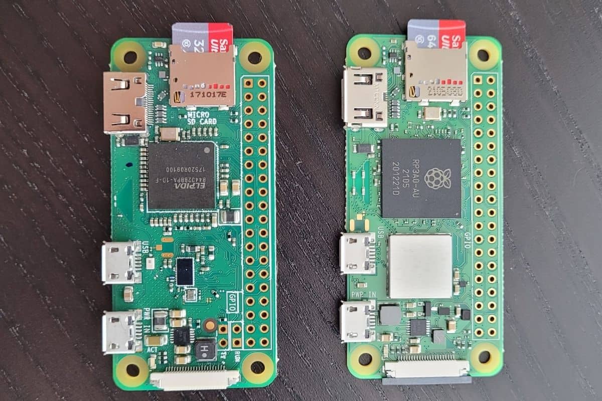
Pi Zero format boards that are supported.

I am interested in the Pi-Zero sized boards. With or without GPIO header soldered on.

I have tracked the original Pi-Zero and it used armv7 and I refrained.

Then came Pi-Zero-2 which upgraded to arm64 processor but it gained a wifi chipset. I prefer wired ethernet. So I refrained.

Both Pi-Zero are supported on FreeBSD I believe.

What about other clones? BananaPi-Zero, Orange-Pi-Zero and Raxda-Zero. Is anybody using a Zero-Clone on FreeBSD?

I am going to take the dive on a Raxda-Zero-3E. It has the feature set I want.
You can get a 1-Gig version for 20 bucks. 4-gig version $32. Zero cases seem somewhat interchangeable.

What are the chances of it working? We have u-boot support for RK3566 I would hope it works like Rock3B.
 
Last edited:
Here is a summary of boards. Listed by processor/soc. Updated as found.

AMLogic (SOC not supported)

Allwinner H

Rockchip:

Broadcom:

Samsung Exonos
 
Last edited:
i have opi zero3 which is most likely the same as opi zero2w + the expansion board. probably the radxa is the better choice. rk3566 > h618
 
The Raspberry Pi Zero 2w is not officially supported by OpenBSD but with a slight fiddle with wifi firmware it works well. On FreeBSD it is officially supported but lacks wifi entirely (though does have better power management!). Since you mentioned you didn't need the wifi, it could be quite ideal for you with FreeBSD.

Currently I am doing some contracting where we are actually using one (running OpenBSD) in the early prototype / breakout board stages. I do recommend it simply because the device itself is so cheap. Because of its popularity, you can basically buy three for the price of any other board.

Pi Zero 2w is advisable compared to the older ones, simply because it is aarch64 (basically a Raspberry Pi 3) vs armhf (basically a Raspberry Pi 1/early 2).

As for the clones, apart from more expensive, I just can't find a confirmation of support. They probably work but only the older NanoPi NEO2 seems to be guaranteed. It is sunxi which is well supported on *BSD (the vendor Linux is typically messy though, avoid).

I am particularly interested in headless devices (GPUs seem pointless on SoCs). If you buy a bunch of these, and I buy another bunch. Perhaps we can compare notes on what works. Might be the only way to find out ;)
 
GPUs seem pointless on SoCs
I couldn't agree more for these Zero Boards.

I like this Raxda RK3366 3E offering but it seems the CPU will be more than I need.
RK3328 would be fine. RK3399 overkill but I see no Zero Boards in that format.

With my adventure in source upgrading I am thinking of concentrating on the 4GB model.
Shame that eMMC is only available on the Zero-3W offering. I dont want the wifi.

Here is the Pi Wiki showing only Zero v1 support. I believe the Pi Zero v2 should work, baring the wifi.
 
Last edited:
A new entry from me. Radxa Rock S0.

Might be a good embedded board for me Ethernet, USB and eMMC option.
RK3308 is low power option compared to RK3566
 
I can confirm that Radxa Rock Zero 3E boots up and works on FreeBSD Current.
eqos Ethernet works too.
Maybe need to buy some POE hats now..

I fried my first one within an hour of Amazon dropping it off.
Warning: These need 5VDC unlike Rock 3A/B/C which take 12VDC+
 
Since the Rock Zero 3E is without RTC I had to enable I2C3 and add DS3231 module.

Code:
ds32310: <Maxim DS3231 RTC> at addr 0xd0 on iicbus1
ds32310: registered as a time-of-day clock, resolution 1.000000s

So GPIO works just like Rock3A/B with overlays applied.

First you need to enable the bus. Only iic0 is enabled by default.
rk3568-i2c3-m0.dts
Code:
/dts-v1/;
/plugin/;

/ {
        metadata {
                title = "Enable I2C3-M0";
                compatible = "radxa,rock-3a", "radxa,rock-3b", "radxa,rock-3c", "radxa,zero3", "radxa,e25";
                category = "misc";
                exclusive = "GPIO1_A0", "GPIO1_A1", "i2c3";
                description = "Enable I2C3-M0.
On Radxa ROCK 3A <= 1.2 this is SDA pin 3 and SCL pin 5.
On Radxa ROCK 3A >= 1.3 this is SDA pin 3 and SCL pin 5.
On Radxa ROCK 3B this is SDA pin 3 and SCL pin 5.
On Radxa ROCK 3C this is SDA pin 3 and SCL pin 5.
On Radxa ZERO 3 this is SDA pin 3 and SCL pin 5.
On Radxa E25 this is SDA pin3 and SCL pin 5.";
        };
};

&i2c3 {
        status = "okay";
        pinctrl-names = "default";
        pinctrl-0 = <&i2c3m0_xfer>;
};
Complie with: dtc -I dts -O dtb -b0 -@ -o rk3568-i2c3-m0.dtb rk3568-i2c3-m0.dts

Now enable my DS3231 RTC module on i2c3 ((this is /dev/iic1 on FreeBSD))
ds3231-rtc-i2c3.dts
Code:
/dts-v1/;
/plugin/;

&i2c3 {
        status = "okay";

        rtc: rtc@68 {
                compatible = "maxim,ds3231";
                reg = <0x68>;
        };
};
Compile with: dtc -I dts -O dtb -b0 -@ -o ds3231-rtc-i2c3.dtb ds3231-rtc-i2c3.dts

Add settings to /boot/loader.conf
Code:
fdt_overlays="rk3568-i2c3-m0.dtb,ds3231-rtc-i2c3.dtb"
ds3231_load=YES

The sysctls with sucessful attachment:
Code:
 # sysctl dev.ds3231
dev.ds3231.0.32khz_enable: 1
dev.ds3231.0.sqw_mode: interrupt
dev.ds3231.0.sqw_freq: 8192
dev.ds3231.0.bbsqw: 0
dev.ds3231.0.temp_conv: 0
dev.ds3231.0.temperature: 36.1C
dev.ds3231.0.%iommu:
dev.ds3231.0.%parent: iicbus1
dev.ds3231.0.%pnpinfo: name=rtc@68 compat=maxim,ds3231
dev.ds3231.0.%location: addr=0xd0
dev.ds3231.0.%driver: ds3231
dev.ds3231.0.%desc: Maxim DS3231 RTC
dev.ds3231.%parent:
 
What are the opinions about powering a board over the GPIO header Power Pins? There are two 5V pins on the header.

What about backfeeding them? The POE hat for this board uses the header to power it.

I have broken the barrier by smoking one already. $28 down the tubes but I did learn from it.

I would like to power the board with "other method" to save a USB jack. It is currently powered by a USB-C connector.
 
What are the opinions about powering a board over the GPIO header Power Pins? There are two 5V pins on the header.
I do that on an Orange Pi Zero 2W. I couldn't find a USB-C cable so just used the 5v VCC from the USB-TTL.

It worked. I fear that it is less regulated so I wouldn't risk doing it via i.e a transformer plug straight into the mains. But the TTL VCC is regulated on the other side (USB), so should be safe.
 
I have a benchtop power supply with amp gauge and I am seeing green LED at 4.3VDC 0.1a load on Rock Zero 3E

Going to test with OS on microSD and cpu stress tests next.
 
/sysutils/stress
Starting at 3 cores testing.
stress --cpu 3
Code:
# sysctl hw.temperature.CPU
hw.temperature.CPU: 56.1C
# sysctl hw.temperature.CPU
hw.temperature.CPU: 57.1C
# sysctl hw.temperature.CPU
hw.temperature.CPU: 57.1C
# sysctl hw.temperature.CPU
hw.temperature.CPU: 57.1C
# sysctl hw.temperature.CPU
hw.temperature.CPU: 59.4C
# sysctl hw.temperature.CPU
hw.temperature.CPU: 61.1C
# sysctl hw.temperature.CPU
hw.temperature.CPU: 61.1C
Seems to have stabilized at 62C
This is with very small heatsink on CPU. Small Ram heatsink too. No fans. Open Air.

Power draw is 0.2 at idle 5DVC and 0.3VDC with the above test running.
 
Stressing all four cores.

Code:
# sysctl hw.temperature.CPU
hw.temperature.CPU: 66.1C
# sysctl hw.temperature.CPU
hw.temperature.CPU: 66.1C
# sysctl hw.temperature.CPU
hw.temperature.CPU: 66.7C
# sysctl hw.temperature.CPU
hw.temperature.CPU: 66.7C
# sysctl hw.temperature.CPU
hw.temperature.CPU: 66.7C
# sysctl hw.temperature.CPU
hw.temperature.CPU: 67.5C
# sysctl hw.temperature.CPU
hw.temperature.CPU: 67.5C
# sysctl hw.temperature.CPU
hw.temperature.CPU: 67.5C
# sysctl hw.temperature.CPU
hw.temperature.CPU: 67.5C

Running hot but not crashing after 10min

Power Draw = 0.4 Amps @ 5VDC
 
I am so happy with this board I am looking at the POE HAT for Radxa Zero 3E

Why would you need a HAT that covers all the pins and offers no breakout?
What good is that? You have Embedded Board with POE and all GPIO pins unusable.
Who designs these things?


They need to drop the fan and add the right passthrough GPIO header.
I can't imagine a 56VDC to 5VDC transformer needing a fan for 400mA. load.
 
and it's overpriced addon too? i guess you could solder to the upper pins on pcb for io...

it's clearly designed for, unsure, what, only usb to network? wifi? video maybe?

that's how i see it. it makes sense then. for gpio, yeah, solder onto pins, create midboard, who knows. needs hacking. or you could just give it a pass
 
okay i checked price afterwards, maybe not that pricey

but other points still stand

unsure, maybe it was too cheap : p
 
I have no gripe with price. It is unsoldering the header that stinks.
I am looking now for blanks on fleabay. This could be a good kit, I like the Phoenix Termnials but would add a barrel jack.
While I am fritzing how about 16M SPI onboard too for uboot......
 
How long would a pair of 16550 batteries power this device during regular usage.. That is in my head..
I am workng on GPS over UART pins now... I have some TTL ublox modules testing.
Trying to decide if I want to use Primary UART for GPS or use an overlay to activate another UART and lose the pins..
 
I am workng on GPS over UART pins now... I have some TTL ublox modules testing.
Trying to decide if I want to use Primary UART for GPS or use an overlay to activate another UART and lose the pins..
Nice. I am working on a GPS project too at the moment. I have so far evaluated two breakout boards:
Both work well via UART (I actually disabled the console on /dev/tty00 to free it up for raw bytes). I make the Raspberry/Orange Pi act as an access point to debug instead.

One note is that Air530 only has support for GPS (only the GPGGA NMEA sentence). Whereas the ublox one has GNSS support (multiple satellite types, GLONAS, etc) and thus has the GNGGA NMEA sentence.

I am doing this as part of some contracting for a small startup. We approached AlphaMicro (ublox partner) and they giggled when I mentioned we used the NEO-6m in our prototype. Apparently it is very old. They pointed us towards some of the more recent eval boards (basically just overpriced breakout boards) using the m10 chip instead.

Edit: That said, there are breakout boards for the M10 too: https://www.amazon.co.uk/SparkFun-GNSS-Receiver-Breakout-Configurable/dp/B0BDBX6K7R (and supports i2c so you don't need to use up a UART)
 
I have to give Radxa props. They have a worthy library of Device Tree Overlays.


I like how they document the pins used by the different boards. It is a great asset.

The rock3 boards all work with the rk3568 overlays above. Plus individual overlays for specialities.

Nice job. I had no idea RK3568 offered so many PWM pins.
 
While the software guys did a good job look at this comment for PWM overlay.

description = "Enable PWM2-M0.\nOn Radxa ROCK 3A <= v1.2 this is pin 17.\nOn Radxa ROCK 3A >= v1.3 this is pin 22.\nOn Radxa ROCK 3B this is pin 22.";

Very nice to document it so well but different pin assignments for different versions of Rock3A is bad.

Plus Rock3E is not in most overlays so I am beta tester.
PDF schematic for Rock 3e is available but Pinout seems to differ slightly from Rock3B which is also RK3566.
So there is Rock 3A with RK3568 and all the other Rock3B/C/E are RK3566. All the overlays are listed as RK3568.
 
Just occured to me I can insert in my compiled DTB overlays to my Poudriere Image overlays to /boot/dtb/overlays
That will be fantastic. Include them in loader.conf overlay too.

My current list of testing overlays on Zero 3E from the Raxda Overlays git cloned.

Working.
RTC on i2c3
ds3231-rtc-i2c3.dts
rk3568-i2c3-m0.dts


Testing. dtb's compiled cleanly with dtc.
i2c1 for gpiolcd
rk3568-i2c1.dts
PWM-2
rk3568-pwm2-m0.dts
SPI-3 Bus
rk3568-spi3-m1-cs1-spidev.dts
Addition UART
rk3568-uart7-m1.dts

Failed with dtc. has #Includes#
OneWire
rk3568-w1-gpio3-a5.dts
 
I found out that Rock Zero 3E uses a different pinout than the Rock3B (also with RK3566 so I assumed the same)
It is much worse than any of the Rock3. I can only have 2 PWM pins after all my busses.
There is even a pin marked NC.


No Connection but schematic says GPIO4_C1
Regardless the muxing sucks on this board.
I get it. Pin traces are so short. Small hardware for package size.

New list of overlays to try.
RTC is already proven but strange that the above documentation does not list pinmux of i2c but the i2c3 overlay is working.
I tried chasing the source and my eyes glazed over chasing stuff in rk3568.dtsi
One Wire excluded for now. Need to build that with gcc.

Some of the bus numbers have changed.
Working:
RTC and i2c3
ds3231-i2c3.dtb
i2c4 bus is generated
i2c4.dtb

Testing
pwm8.dtb
pwm9.dtb
spi3.dtb
uart5.dtb
 
Back
Top