GPIO API general (Orange Pi ... H3)

try this
Code:
/dts-v1/;
/plugin/;

/ {
    compatible = "allwinner,sun8i-h3";

    fragment@0 {
        target = <&spi0>;
        __overlay__ {
            status = "okay";
    spigen {
     compatible = "freebsd,spigen";
     status = "okay";
     reg = <0>;
     spi-max-frequency = <1000000>;
     };   
        };
    };

    fragment@1 {
        target = <&spi1>;
         __overlay__ {
            status = "okay";
            spigen {
             compatible = "freebsd,spigen";
             status = "okay";
             reg = <0>;
             spi-max-frequency = <1000000>;
             };   
        };
    };
};
 
Thank you, man!
You make my day!
Now I have devices /dev/spigen0.0 and /dev/spigen1.0 and they working with SPI()
:~ # spi -i
Device name: /dev/spigen0.0
Device mode: 0
Device speed: 1000000
:~ # spi -f /dev/spigen1.0 -i
Device name: /dev/spigen1.0
Device mode: 0
Device speed: 1000000
 
i don't know of any definitive resource
this i adapted from armbian / github
i've got somewhat familiar by playing with u-boot / linux / bsd on various arm hardware
 
That overlay created the devices, but I am not sure if those devices would actually work.

A much simpler overlay that worked for me (on Orange Pi PC Plus): https://cgit.FreeBSD.org/src/commit/?id=b8db946c3b4498d9d2b22d3cd184b2c5033ade73

Ah, I see why you added spigen nodes, without those there obviously won't be /dev/spigen devices.
I opted to configure spigen via hints (in loader.conf):
Code:
hint.spigen.0.at="spibus0"
hint.spigen.0.clock="60000000"
hint.spigen.0.mode="0"
hint.spigen.0.cs="0"
 
Where can I find documentation on how to write and compile dts files?
I think its interesting to decompile your boards dtb. Good practice on using the dtc.
Because the dtb pulls in stuff from many include files it is interesting to study the end product.
Compare that against ofwdump results.

For professional tools NXP has a toolkit for iMX6 that is a GUI representation of the pin header.
You click on a pin and tell it what you want it to do and it writes out to the device tree file.

So caveman compared to modern tools. Many ways to do it. Lots of elaborate bracketry.
Finding where to stab in the fragment in the device tree can be the challenging part.

 
That overlay created the devices, but I am not sure if those devices would actually work.

A much simpler overlay that worked for me (on Orange Pi PC Plus): https://cgit.FreeBSD.org/src/commit/?id=b8db946c3b4498d9d2b22d3cd184b2c5033ade73

Ah, I see why you added spigen nodes, without those there obviously won't be /dev/spigen devices.
I opted to configure spigen via hints (in loader.conf):
Code:
hint.spigen.0.at="spibus0"
hint.spigen.0.clock="60000000"
hint.spigen.0.mode="0"
hint.spigen.0.cs="0"
Thank you, man!
This way also works for me, just you make a mistake clock=60Mhz I correct to 6Mhz and:
:~ # spi -i
Device name: /dev/spigen0.0
Device mode: 0
Device speed: 6000000

Also, I make a file sun8i_andriy.dts:
Code:
/dts-v1/;
/plugin/;

/ {
    compatible = "allwinner,sun8i-h3";
};
&{/soc/spi@1c68000} {
    status = "okay";
};
and compiled it:
dtc -O dtb -I dts sun8i_andriy.dts >/boot/dtb/overlays/sun8i-h3-spi0.dtso
and added lines to /boot/loader.conf:
Code:
fdt_overlays="sun8i-h3-spi0.dtso"
hint.spigen.0.at="spibus0"
hint.spigen.0.clock="6000000"
hint.spigen.0.mode="0"
hint.spigen.0.cs="0"
hint.spigen.1.at="spibus1"
hint.spigen.1.clock="6000000"
hint.spigen.1.mode="0"
hint.spigen.1.cs="0"
After rebooting:
:~ # spi -i
Device name: /dev/spigen0.0
Device mode: 0
Device speed: 6000000
:~ % sudo spi -f /dev/spigen1.0 -i
Device name: /dev/spigen1.0
Device mode: 0
Device speed: 6000000
 
The clock can be dynamically changed, so the initial value is not always important.
spi -s 3000000
Okay, it's just reporting an error when the clock was 60000000 ...
Sorry, an error was using cmd without SUDO()
:~ % spi -i
Error - unable to open '/dev/spigen0.0', errno=13
 
I would like to steal this work for iMX6 Hummingboard. Can you help me. Here are my spi nodes:

Code:
HB2-GATE:~ # ofwdump -a|grep spi
        Node 0x1970: spi@2008000
        Node 0x1a84: spi@200c000
        Node 0x1bd0: spi@2010000
        Node 0x1ce4: spi@2014000
          Node 0x56dc: hummingboard2-ecspi2grp

Which node should I use for my DT setting?

Code:
/dts-v1/;
/plugin/;

/ {
    compatible = ""fsl,imx6q";
};
&{/soc/spi@2008000} {
    status = "okay";
};

Who can comment on these 'grp' nodes I see here (ecspi2grp) and I see the same for pwm.
A grp node under the parent.
 
Very nice work. Compiled the above and added hints.
Code:
imx_spi0: <i.MX ECSPI Master> mem 0x200c000-0x200ffff irq 61 on simplebus2

Code:
HB2-GATE:~ # spi -i
Device name:   /dev/spigen0.0
Device mode:   0
Device speed:  6000000
 
Congrats, thanks to Andriy & covacat!

At my dmesg I see spibus1 too ... for that reason, I added hints for spigen1.
If you see at yours spibus1 & 2 & 3, you can add all that hints for them.
 
I have some temperature chips for a work project.
MAX31855 Thermocouple Modules.
They need 3 SPI lines. DO, CS and CLK
How do I use this? Three signal pins needed?
 
Yes 3 pins at least (+ two for power). You need just one SPI channel (spigen0.0).
DO = SPI0_MOSI
CS = SPI0_CS
CLK = SPI0_CLK
Please give me a time if you need more information.
 
I think I have found what I need. I need to be using spi1 for ecspi2

From imx6qdl-hummingboard.dtsi

pinctrl_hummingboard2_ecspi2: hummingboard2-ecspi2grp {
fsl,pins = <
MX6QDL_PAD_EIM_OE__ECSPI2_MISO 0x100b1
MX6QDL_PAD_EIM_CS1__ECSPI2_MOSI 0x100b1
MX6QDL_PAD_EIM_CS0__ECSPI2_SCLK 0x100b1
MX6QDL_PAD_EIM_RW__GPIO2_IO26 0x000b1 /* CS */

Snippet from imx6qdl.dtsi
Aliases
spi0 = &ecspi1;
spi1 = &ecspi2;
spi2 = &ecspi3;
spi3 = &ecspi4;
 
pinctrl_hummingboard2_ecspi2: hummingboard2-ecspi2grp {
fsl,pins = <
MX6QDL_PAD_EIM_OE__ECSPI2_MISO 0x100b1
MX6QDL_PAD_EIM_CS1__ECSPI2_MOSI 0x100b1
MX6QDL_PAD_EIM_CS0__ECSPI2_SCLK 0x100b1
MX6QDL_PAD_EIM_RW__GPIO2_IO26 0x000b1 /* CS */
So I am going to assume here that grp=pin group.
GPIO2_IO26 is an accessible pin.
Maybe this is the control pin for the ecspi2 pin group.

CLK=Clock
MOSI=DO
MISO=DI
GPIO2_IO26=CS
 
1644721014303.png

:P
 
I was wondering why is ecspi starting at ecspi2.
Looking at mx6dl_pins.h I see that ecspi1 is mapped to CSI0. That is the Pi-Like Camera interface.
MX6_PAD_DECL(CSI0_DAT5__ECSPI1_MOSI, 0x038C, 0x0078, 2, 0x07E0, 0, 0)
 
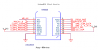
I had to go to the schematic for the pin locations. The ecspi2 pins are located on the mikrobus socket connectors.
 

Attachments

  • mikrobus.png
    mikrobus.png
    38.5 KB · Views: 130
I can't seem to activate more than one SPI bus. Its not the overlays or loader hints.
It just crashes on bootup with two SPI buses. So I am going to concentrate on one SPI bus. It is all I need.

Any recommendations on the dumbest SPI device for a slave? I want something simple for learning SPI.
 
The choice for my taste is something like this.
Moreover, I have one such device, I just haven't tried to connect it to the NUCLEO 64 (STM32) board.
 
I am looking at the ADC boards too.
ADS1118

I wish I could find a module with mcp3008.

So whats the story on drivers. Would I need a FreeBSD driver for mcp3008 or is SPI comms enough?
 

I can't say for sure, but I don't think mcp3008 will need any drivers. I am now experimenting with a 128X160 SPI ST7735S TFT LCD ... I was able to initialize the device and print the background color as desired all with one shell script full of SPI() and GPIOCTL() commands ...
I will publish the results soon.
 
Back
Top